Voice Controlled Home automation using Bluetooth
- Ramesh G
- Nov 30, 2020
- 4 min read
Updated: Jul 2, 2021
Here is a simple tutorial for interfacing an Android smartphone with Arduino via Bluetooth!
The main parts to this project. An Android smartphone and application, a Bluetooth transceiver, and an Arduino. We just need an Arduino UNO to serially communicate with HC-05 Bluetooth module and a smartphone to send voice command to Bluetooth module HC-05.
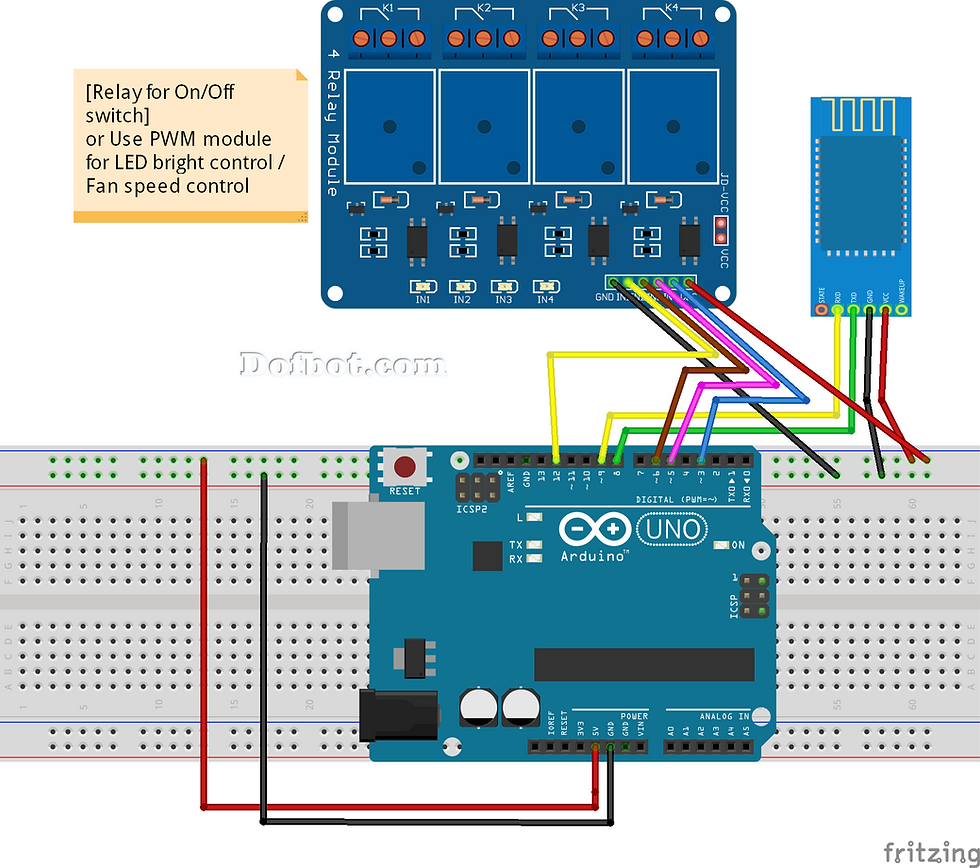
Circuit Diagram:

Connection made as per circuit diagram.
The Following parts are required for this project:
1) Arduino Uno R3
2) HC-05 or HC-06
3) 4 channel Relay module
4) Android smartphone
5) 9V power supply
Make the circuit as is given by the circuit diagram. Make the robot assembly with your selected parts and connect the motors to the circuit.
1) The VCC of HC-05 to 5V of Arduino
2) The GND of HC-05 to GND of Arduino
3) The TX of HC-05 to RX of Arduino (Digital power pin 0)
4) The RX of HC-05 to TX of Arduino (Digital power pin 1)
Then Power on the Arduino. The HC-05 should power up if all connections are perfect. The LED on the HC-05 Module will continuously blink which means the device is now discoverable.
When you are connecting to the Bluetooth module for the first time, it will ask you the password. Enter 0000 OR 1234.
When the device gets successfully paired with the android smart phone.
The Arduino Bluetooth module at the other end receives the data and sends it to the Arduino through the TX pin of the Bluetooth module (connected to RX pin of Arduino)
The idea is to use the App to turn ON and OFF the LEDS and also controlling their intensity.
Connections:
Device 1: “device1on / device1off” ==> LED Red ==> Pin 3 UNO
Device 2: “device2on / device2off” ==> LED Yellow ==> Pin 5 of the UNO
Device 3: “device3on / device3off” ==> LED Green ==> Pin 6 UNO
Device 4: “device4on / device4off” ==> LED Blue ==> Pin 9 of the UNO
Loop:
{
while (BT.available()) //Check if there is an available byte to read
{
delay(10); //Delay added to make thing stable
char c = BT.read(); //Conduct a serial read
device += c; //build the string.
}
if (device.length() > 0)
{
Serial.println(device);
// Button control:
if (device == "One") {digitalWrite(Device1, HIGH);}
else if (device == "Two") {digitalWrite(Device1, LOW);}
else if (device == "Three") {digitalWrite(Device2, HIGH);}
else if (device == "Four") {digitalWrite(Device2, LOW);}
else if (device == "Five") {digitalWrite(Device3, HIGH);}
else if (device == "Six") {digitalWrite(Device3, LOW);}
else if (device == "Seven") {digitalWrite(Device4, HIGH);}
else if (device == "Eight") {digitalWrite(Device4, LOW);}
That is, to trigger the “ON” related to “Device 1” button, the text message “device1on” will be sent to the Arduino. Upon receiving this message, the red LED should light and so on.
Note that the 4 pins are the pins capable of generating PWM. This is important for the use of “sliders” at the App, to send numeric data to control the intensity of the LEDs through PWM:
Device A0: “r / 0-255” ==> LED Red ==> Pin 3 UNO
Device A1 “y / 0-255” ==> LED Yellow ==> Pin 5 of the UNO
Device A2: “g / 0-255” ==> LED Green ==> Pin 6 UNO
Device A3: “b / 0-255” ==> LED Blue ==> Pin 9 do UNO
In the case of sliders, before the PWM data value (0 to 255), a character is sent to the Arduino to inform it that a ”slider” command is coming.
In the video bellow, a demonstration of the portion above program (Buttons & Slider):
The slider code:
// Slider control:
char colour = device[0];
int value = device[2];
Serial.print(" ");
Serial.println(value);
if ( colour == 'r') //RED LED
{
analogWrite(Device1, value); // use value to set PWM for LED brightness
}
if ( colour == 'y') //yellow LED
{
analogWrite(Device2, value); // use value to set PWM for LED brightness
}
if ( colour == 'g') //green LED
{
analogWrite(Device3, value); // use value to set PWM for LED brightness
}
if ( colour == 'b') //BLUE LED
{
analogWrite(Device4, value);
}
device=""; //Reset the variable
}
The following voice command to control the LED on/off through voice to text command from android device through bluetooth HC-05. The bluetooth sent text data to the arduino and control LED on/off respectively.
// Voice control:
else if (device == "TV on" || device == "turn on TV") {digitalWrite(Device1, HIGH);}
else if (device == "TV off" || device == "turn off TV") {digitalWrite(Device1, LOW);}
else if (device == "light on" || device == "turn on light") {digitalWrite(Device2, HIGH);}
else if (device == "light off" || device == "turn off light") {digitalWrite(Device2, LOW);}
else if (device == "fan on" || device == "turn on fan") {digitalWrite(Device3, HIGH);}
else if (device == "fan off" || device == "turn off fan") {digitalWrite(Device3, LOW);}
else if (device == "5" || device == "turn on AC") {digitalWrite(Device4, HIGH);}
else if (device == "7" || device == "turn off AC") {digitalWrite(Device4, LOW);}
ANDROID APPLICATION
The Android app developers generally use JAVA language, but this Android app can also build without knowing the Java language. This app was developed in the online Development Environment which is developed by MIT called “App Inventor”. This app inventor is specially designed for Block programmers those who don’t know the JAVA language. The app shown below has buttons and all the buttons give different bytes in the output that has to be sent to the Arduino using Bluetooth for processing.


Demo:
Download code:
Subscribe and Download code.

Comments