
RF Encoder and Decoder interface with Arduino
- Ramesh G
- Feb 14, 2021
- 3 min read
Updated: Jul 2, 2021
This tutorial to learn, One of the easiest and cheapest ways to implement wireless communication is using RF Module (Radio Frequency Module). The transmitter circuit is built encoder HT12E Module , 433MHz RF transmitter module (TX) and a few discrete components. The receiver circuit is built around Arduino UNO board, decoder HT12D Module, 433MHz RF receiver module (RX), 4 LED and a few discrete components.
Components required
433 MHz RF Transmitter and Receiver Module
HT12D Decoder Module
HT12E EncoderModule
Push Buttons (4 Nos)
LEDs (4 Nos)
Arduino Uno
433MHz RF Transmitter and Receiver Module:
This hybrid RF Transceiver Module provides a complete RF transmitter and receiver module solution which can be used to transmit data at up to 3KHz from any standard CMOS/TTL source.
The transmitter module is very simple to operate and offers low current consumption (typical. 11mA). Data can be supplied directly from a microprocessor or encoding device, thus keeping the component count down and ensuring a low hardware cost.

The RX – ASK is an ASK Hybrid receiver module. The RF Transmitter Receiver Module is an effective low-cost solution for using 433 MHz. The TX-ASK is an ASK hybrid transmitter module. TX-ASK is designed by the saw resonator, with an effective low cost, small size and simple to use for designing.
Specifications of 433MHz RF Transmitter Receiver Wireless Module:
Range in open space(Standard Conditions) : 100 Meters RX Receiver Frequency : 433 MHz RX Typical Sensitivity : 105 Dbm RX Supply Current : 3.5 mA RX IF Frequency : 1MHz RX Operating Voltage : 5V TX Frequency Range : 433.92 MHz TX Supply Voltage : 3V ~ 6V TX Out Put Power : 4 ~ 12 Dbm
Features of 433MHz RF Transmitter Receiver Wireless Module:
Low Power Consumption Easy For RF based Application Complete Radio Transmitter Transmit Range Up To 50m CMOS / TTL Input No Adjustable Components Very Stable Operating Frequency Low Current Consumption (Typ 11mA) Wide Operating Voltage ASK Modulation
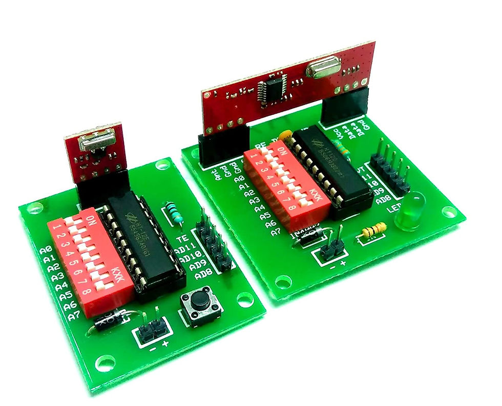
RF Encoder Decoder Module Board

The module is a pair of Encoder & Decoder Boards. The entire module is quite easy to use and is compatible with most of the old and new versions of Arduino/Raspberry Pi, PIC boards or projects.
Features RF Encoder Decoder Module Board:
Easy interfacing with the RF modules, using the female headers for placing the modules. Breakout pins for connecting to the microcontroller. DIP Switch for Address Selection (when multiple modules are used at one location) Status LED for valid transmit. Supports both ASK, FSK RF modules Small size, high quality PCB.
433MHz RF Transmitter and Receiver with RF Encoder Decoder Module:
Circuit Connection
Transmitter circuit
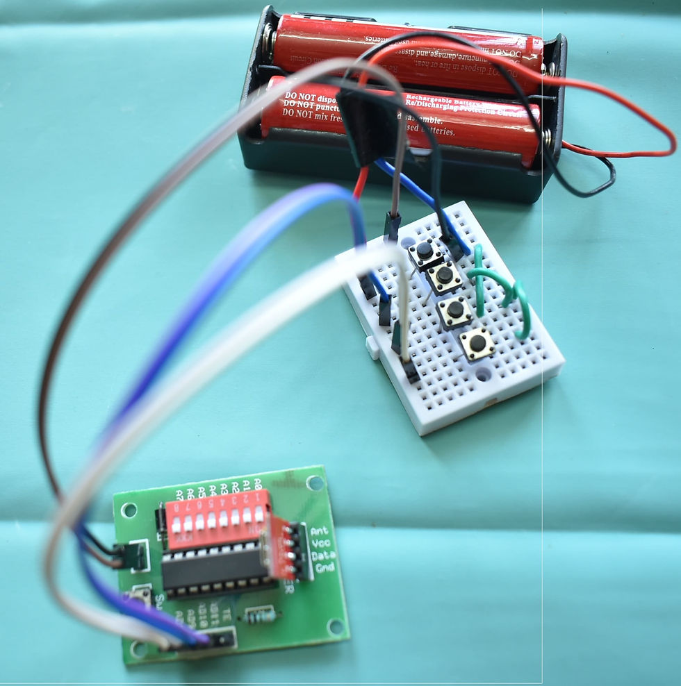
Push Button Switches S1, S2, S3 and S4 are interfaced with AD8 through AD11 of encoder HT12E Module.
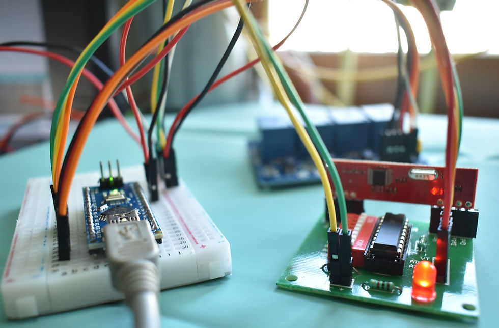
Receiver circuit
Arduino Pin D2 to D5 are Connected to AD8 through AD11 of Decoder HT12D Module.
Arduino Pin D8 to D11 are Connected to LED or Relay.
Subscribe and Download code.

Subscribe and Download code.
arduino code
//// WWW.DOFBOT.COM
int sw1 =2;
int sw2 =3;
int sw3 =4;
int sw4 =5;
int out1=8;
int out2=9;
int out3=10;
int out4=11;
void setup()
{
pinMode(sw1,INPUT);
pinMode(sw2,INPUT);
pinMode(sw3,INPUT);
pinMode(sw4,INPUT);
pinMode(out1,OUTPUT);
pinMode(out2,OUTPUT);
pinMode(out3,OUTPUT);
pinMode(out4,OUTPUT);
}
void loop()
{
if ((digitalRead(sw1)==LOW) && (digitalRead(sw2)==HIGH) && (digitalRead(sw3)==HIGH) && (digitalRead(sw4)==HIGH))
{
RELAY1();
}
else if ((digitalRead(sw1)==HIGH) && (digitalRead(sw2)==LOW) && (digitalRead(sw3)==HIGH) && (digitalRead(sw4)==HIGH))
{
RELAY2();
}
else if ((digitalRead(sw1)==HIGH) && (digitalRead(sw2)==HIGH) && (digitalRead(sw3)==LOW) && (digitalRead(sw4)==HIGH))
{
RELAY3();
}
else if ((digitalRead(sw1)==HIGH) && (digitalRead(sw2)==HIGH) && (digitalRead(sw3)==HIGH) && (digitalRead(sw4)==LOW))
{
RELAY4();
}
else
{ digitalWrite(out1,LOW);
digitalWrite(out2,LOW);
digitalWrite(out3,LOW);
digitalWrite(out4,LOW);
}
}
void RELAY1()
{ digitalWrite(out1,HIGH);
digitalWrite(out2,LOW);
digitalWrite(out3,LOW);
digitalWrite(out4,LOW);
}
void RELAY2()
{ digitalWrite(out1,LOW);
digitalWrite(out2,HIGH);
digitalWrite(out3,LOW);
digitalWrite(out4,LOW);
}
void RELAY3()
{ digitalWrite(out1,LOW);
digitalWrite(out2,LOW);
digitalWrite(out3,HIGH);
digitalWrite(out4,LOW);
}
void RELAY4()
{ digitalWrite(out1,LOW);
digitalWrite(out2,LOW);
digitalWrite(out3,LOW);
digitalWrite(out4,HIGH);
}
Comments