
IR Remote Controlled 4 channel relay
- Ramesh G

- Mar 27, 2022
- 4 min read
In this Project TSOP1738 IR receiver to control a relay board using Arduino nano and LCD. The LCD to display the relay ON/OFF status of 4 channel relay board. The relay module is used to automate them the electrical appliances.

Components required
TSOP 1738 IR receiver - 1no
Arduino Nano - 1 no
LCD1602 with I²C - 1no
IR remote (HM23) - 1no
4 Channel Relay Module (HW316)- 1no
Circuit diagram
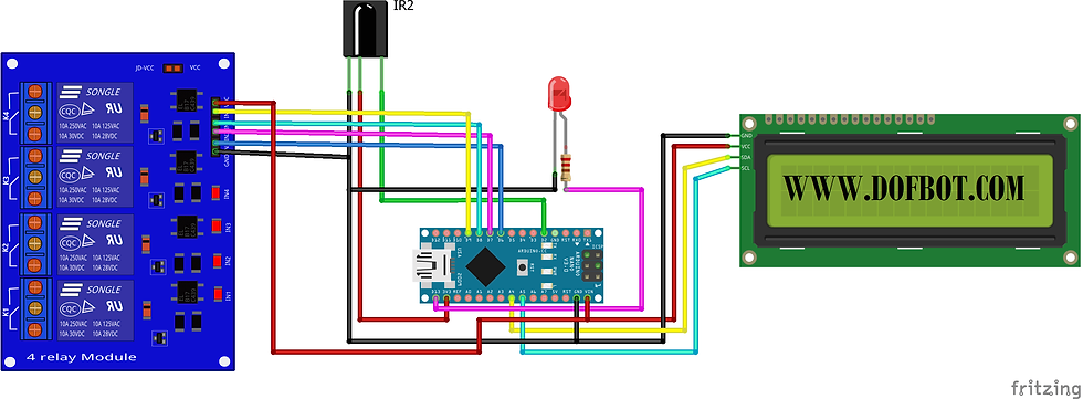
4 Channel Relay Module
The four-channel relay module contains four 5V relays and the associated switching and isolating components, which makes interfacing with a microcontroller or sensor easy with minimum components and connections. The contacts on each relay are specified for 250VAC and 30VDC and 10A in each case, as marked on the body of the relays.
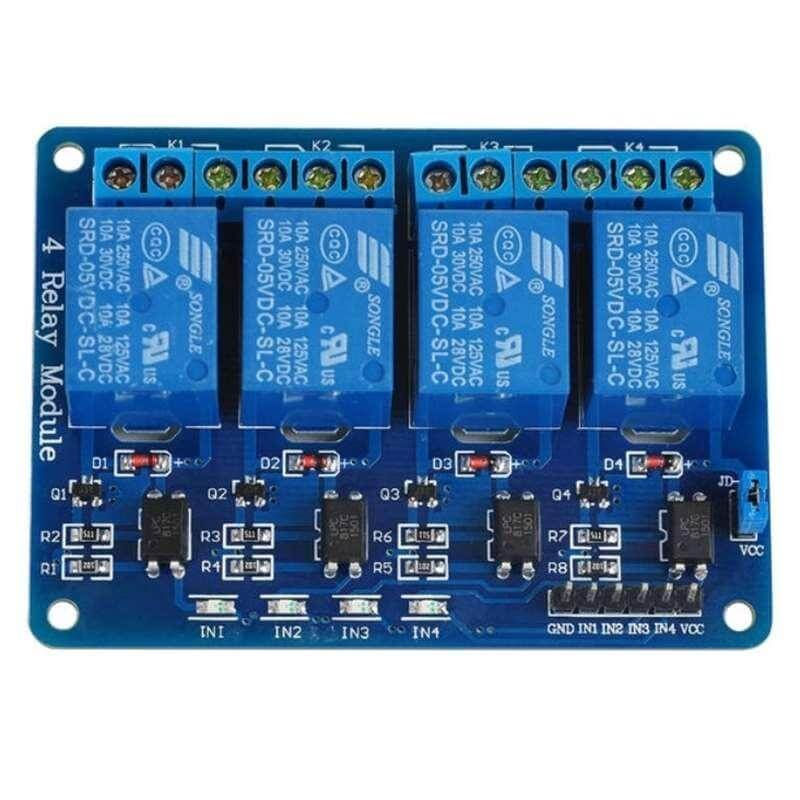
Internal circuit
Each relay on the board has the same circuit, and the input ground is common to all four channels.
The driver circuit for this relay module is slightly different compared to traditional relay driving circuits since there is an optional additional layer of isolation. When the jumper is shorted, the relay and the input share the same VCC, and when it is open, a separate power supply must be provided to the JD-VCC jumper to power the relay coil and optocoupler output.
The inputs for this module are active low, meaning that the relay is activated when the signal on the input header is low. This is because the indicator LED and the input of the optocoupler are connected in series to the VCC pin on one end, so the other end must be connected to the ground to enable the current flow. The optocouplers used here are the PCF817, which is a common optocoupler and can also be found in through-hole packaging.

How To Use The Four-Channel Relay Module
The four-channel can be used to switch multiple loads at the same time since there are four relays on the same module. This is useful in creating a central hub from where multiple remote loads can be powered. It is useful for tasks like home automation where the module can be placed in the main switchboard and can be connected to loads in other parts of the house and can be controlled from a central location using a microcontroller.
In this diagram, four separate loads (represented by lightbulbs) have been connected to the NO terminals of the relay. The live wire has been connected to the common terminal of each relay. When the relays are activated, the load is connected to the live wire and is powered. This setup can be reversed by connecting the load to the NC terminal that keeps it powered on till the relay is activated.
Download DATASHEET
TSOP1738(SM0038)

The TSOP sensor has the ability to read the output signals from home remotes like TV remote, Home theatre remote, AC remote etc. All these remotes will work with a frequency of 38kHz and this IC can pick up any IR signals process them and provide the output on pin 3. So if you are looking for a sensor to analyse, re-create or duplicate the functions of a remote then this IC will be the perfect choice for you.

Also keep in mind that this series TSOP-1738 will receive only 38Khz IR signals. All remotes in India will operate in 38Khz, kindly ensure if it is the same in your country.
The TSOP-1738 is an IR Receiver Sensor, which can be used to receive IR signals of 38Khz. The sensor operates on 5V and consumes around 5mA to operate. Normally the signal pin (pin 3) IC is connected to a microcontroller to analyse the IR signal received.


Installing Library
Infrared receiver: you need to download and install the IR library.
LiquidCrystal_I2C.h : you need to Download and install the LiquidCrystal_I2C library.
Follow the next steps to install those libraries.
In your Arduino IDE, to install the libraries go to Sketch > Include Library > Add .ZIP library… and select the library you’ve just downloaded.
After installing the required libraries, copy the following code to your Arduino IDE.
Refer IR decoder project for IR remote code .https://www.dofbot.com/post/ir-decoder-with-data-acquisition-tool
Arduino Code
#include <IRremote.h>
int IRPIN = 2;
IRrecv irrecv(IRPIN);
decode_results results;
#include <LiquidCrystal_I2C.h>
LiquidCrystal_I2C lcd(0x27,16,2); // set the LCD address to 0x27 for a 16 chars and 2 line display
int Relay1 = 6; //Relay1
int Relay2 = 7; //Relay2
int Relay3 = 8; //Relay3
int Relay4 = 9; //Relay4
int LED = 13; //LED indiacator
int STATE1 = 0; //Indicates state of Relay1 (OFFboard LED)
int STATE2 =0; //Indicates state of Relay2 (OFFboard LED)
int STATE3 = 0; //Indicates state of Relay3 (OFFboard LED)
int STATE4 =0; //Indicates state of Relay4 (OFFboard LED)
int STATE5 =0; //Indicates state of Relay1 to 5 (OFFboard LED)
void setup()
{
Serial.begin(9600);
Serial.println("Enabling IRin");
irrecv.enableIRIn(); //Starts receiving
Serial.println("Enabled IRin");
pinMode(Relay1, OUTPUT);
pinMode(Relay2, OUTPUT);
pinMode(Relay3, OUTPUT);
pinMode(Relay4, OUTPUT);
pinMode(Relay1, HIGH); //Turns Relay1 OFFby default
pinMode(Relay2, HIGH); //Turns Relay2 OFFby default
pinMode(Relay3, HIGH); //Turns Relay3 OFFby default
pinMode(Relay4, HIGH); //Turns Relay4 OFFby default
pinMode(LED, OUTPUT);
lcd.init(); // initialize the lcd
// Print a message to the LCD.
lcd.backlight();
lcd.setCursor(0,0);
lcd.print(" INFRARED HOME ");
lcd.setCursor(0,1);
lcd.print("AUTOMATION");
delay(1000);
lcd.clear();
lcd.setCursor(0,0);
lcd.print("RL1 RL2 RL3 RL4");
lcd.setCursor(0,1);
lcd.print("ON ON ON ON ");
}
void loop()
{
if(irrecv.decode(&results))
{
digitalWrite(LED, HIGH); //turn LED ON
delay(250);
digitalWrite(LED, LOW); //turn LED OFF
Serial.println(results.value, HEX);
irrecv.resume();
if(results.value==0x1FE50AF) // IR code case1
{
if(STATE1 == 0) //If state is 0, relay 1 OFF
{
digitalWrite(Relay1, HIGH); //turn OFF Relay1
STATE1 = 1;
lcd.setCursor(0,1);
lcd.print("OFF");
}
else if(STATE1 == 1) //If state is 1, relay 1 ON
{
digitalWrite(Relay1,LOW); //turn ON Relay1
STATE1 = 0;
lcd.setCursor(0,1);
lcd.print("ON ");
}
}
if(results.value==0x1FED827) // IR code case2
{
if(STATE2 == 0) //If state is 0, relay 2 OFF
{
digitalWrite(Relay2, HIGH); //turn OFF Relay2
STATE2 = 1;
lcd.setCursor(4,1);
lcd.print("OFF");
}
else if(STATE2 == 1) //If state is 1, relay 2 ON
{
digitalWrite(Relay2,LOW); //turn ON Relay2
STATE2 = 0;
lcd.setCursor(4,1);
lcd.print("ON ");
}
}
if(results.value==0x1FEF807) // IR code case3
{
if(STATE3 == 0) //If state is 0, relay 3 OFF
{
digitalWrite(Relay3, HIGH); //turn OFF Relay3
STATE3 = 1;
lcd.setCursor(8,1);
lcd.print("OFF");
}
else if(STATE3 == 1) //If state is 1, relay 3 ON
{
digitalWrite(Relay3,LOW); //turn ON Relay3
STATE3 = 0;
lcd.setCursor(8,1);
lcd.print("ON ");
}
}
if(results.value==0x1FE30CF) // IR code case3
{
if(STATE4 == 0) //If state is 0, relay 4 OFF
{
digitalWrite(Relay4, HIGH); //turn OFF Relay4
STATE4 = 1;
lcd.setCursor(12,1);
lcd.print("OFF");
}
else if(STATE4 == 1) //If state is 1, relay 4 ON
{
digitalWrite(Relay4,LOW); //turn ON Relay4
STATE4 = 0;
lcd.setCursor(12,1);
lcd.print("ON ");
}
}
irrecv.resume(); //Ready to receive next data
}
}
Serial monitor
After a successful upload, open the Serial Monitor at a baud rate of 9600. see the IR decoder received code result on Serial monitor.

Demo


Comments