In this tutorial we will learn how to interface an IoT Based Tilt Position Monitoring canvas gauge using Nodemcu ESP826612E and KY-017 Mercury Magic Cup Tilt Switch Module.

This Mercury Switch is an electronic device used to detect the orientation or tilting of an object and provides digital output based on the orientation. It behaves like a normal ON – OFF switch that is controlled by tilting. Tilt sensor consists of a mercury ball and two contacts in a sealed Bulp, in which the mercury ball will short the leads based on the orientation.
Components Required
ESP8266 NodeMCU Dev Board
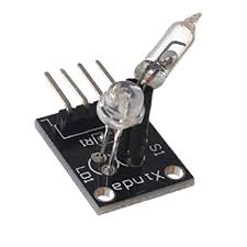
KY-017 - Magic Cup Tilt switch (Mercury)
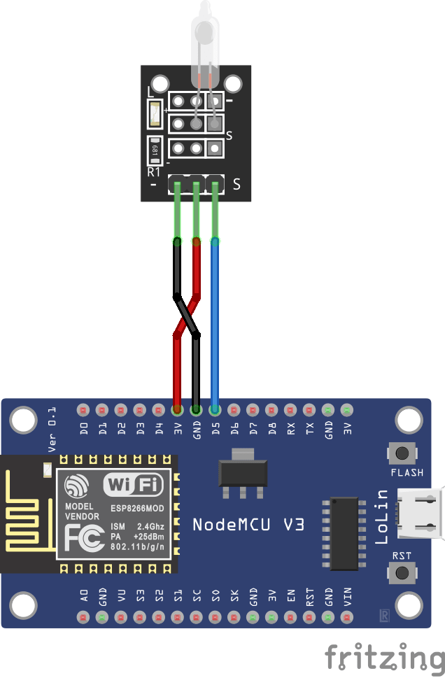
Circuit diagram

KY-017 - Magic Cup Tilt switch (Mercury)

Magic Light Cup Module is a board which has a led and a mercury tilt switch. Using PWM to drive the LEDs on the module you can achieve the effect of light being “magically” transferred from one module to the other when tilting them. In short, it’s 2 components combined, a mercury tilt switch and a led. On tilting the module mercury inside small tube connect the switching point and make switch ON while tilting it to other side move the mercury and it disconnects the circuit and switch get OFF. The module operates on 5V DC supply. So the magic in the name of this module is because when you tilt the switch, the led will turn on and off. And Of course, it is also possible to connect it to the NodeMCU. Pin Connection with Node MCU:
Connect G to a GND port of your NodeMCU
Connect + to a 3.3v port of your NodeMCU
Connect S to a digital port on your NodeMCU (in my example port D5)
Connect L to a digital port on your NodeMCU (in my example port 3.3V)
working Principle
Not Tilted
When the sensor is in “Not Tilted” position, the mercury ball will be at the bottom and shorting the contacts as shown in the image below. This will turn ON the LED and the output will be LOW.
Tilted
When the sensor is in “Tilted” position, the mercury ball will move away from the contacts as shown in the image below. This will turn OFF the LED and the output will be HIGH.
Subscribe and Download code.
Arduino Code
#include <ESP8266WiFi.h>
#include <ESP8266WebServer.h>
#include <FS.h> //Include File System Headers
const char* htmlfile = "/index.html";
//WiFi Connection configuration
const char* ssid = "TP-Link_3200"; //Your Wifi SSID
const char* password = "9500112137"; //Your Wiffi PAssword
ESP8266WebServer server(80);
void handleADC(){
if (digitalRead(14) == 1)
{
delay(300);
}
else
(digitalRead(14) == 0);
{
delay(300);
}
String adc = String(digitalRead(14));
Serial.println(adc);
server.send(200, "text/plane",adc); //sends data to server
}
void handleRoot(){
server.sendHeader("Location", "/index.html",true); //Redirect to our html web page
server.send(302, "text/plane","");
}
void handleWebRequests(){
if(loadFromSpiffs(server.uri())) return;
String message = "File Not Detected\n\n";
message += "URI: ";
message += server.uri();
message += "\nMethod: ";
message += (server.method() == HTTP_GET)?"GET":"POST";
message += "\nArguments: ";
message += server.args();
message += "\n";
for (uint8_t i=0; i<server.args(); i++){
message += " NAME:"+server.argName(i) + "\n VALUE:" + server.arg(i) + "\n";
}
server.send(404, "text/plain", message);
Serial.println(message);
}
void setup() {
delay(1000);
pinMode(14, INPUT);
Serial.begin(115200);
Serial.println();
//Initialize File System
SPIFFS.begin();
Serial.println("File System Initialized");
Serial.print("Setting AP (Access Point)…");
Serial.println();
WiFi.begin(ssid, password); // Connect to the network
Serial.print("Connecting to ");
Serial.print(ssid); Serial.println(" ...");
// Wait for connection
while (WiFi.status() != WL_CONNECTED) {
delay(500);
Serial.print(".");
}
//If connection successful show IP address in serial monitor
Serial.println("");
Serial.print("Connected to ");
Serial.println(ssid);
Serial.print("IP address: ");
Serial.println(WiFi.localIP()); //IP address assigned to your ESP
//Initialize Webserver
server.on("/",handleRoot);
server.on("/getADC",handleADC); //Reads ADC function is called from out index.html
server.onNotFound(handleWebRequests); //Set setver all paths are not found so we can handle as per URI
server.begin();
Serial.println("HTTP server started");
}
void loop() {
server.handleClient();
}
bool loadFromSpiffs(String path){
String dataType = "text/plain";
if(path.endsWith("/")) path += "index.htm";
if(path.endsWith(".src")) path = path.substring(0, path.lastIndexOf("."));
else if(path.endsWith(".html")) dataType = "text/html";
else if(path.endsWith(".htm")) dataType = "text/html";
else if(path.endsWith(".css")) dataType = "text/css";
else if(path.endsWith(".js")) dataType = "application/javascript";
else if(path.endsWith(".png")) dataType = "image/png";
else if(path.endsWith(".gif")) dataType = "image/gif";
else if(path.endsWith(".jpg")) dataType = "image/jpeg";
else if(path.endsWith(".ico")) dataType = "image/x-icon";
else if(path.endsWith(".xml")) dataType = "text/xml";
else if(path.endsWith(".pdf")) dataType = "application/pdf";
else if(path.endsWith(".zip")) dataType = "application/zip";
File dataFile = SPIFFS.open(path.c_str(), "r");
if (server.hasArg("download")) dataType = "application/octet-stream";
if (server.streamFile(dataFile, dataType) != dataFile.size()) {
}
dataFile.close();
return true;
}
Then, upload the code to your NodeMCU board. Make sure you have selected the right board and COM port. Also, make sure you’ve inserted your WiFi Credentials in the code.

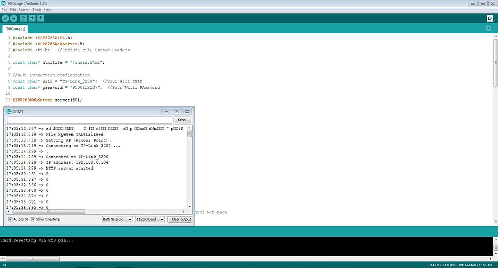
After a successful upload, open the Serial Monitor at a baud rate of 115200. Press the “EN/RST” button on the ESP8266 board. Now it should print its IP address


Comments