IoT Based Internet Clock using Dot Matrix Display
- Ramesh G
- Jan 30, 2021
- 3 min read
Updated: Jul 2, 2021
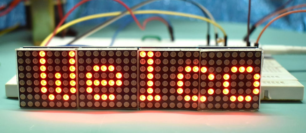
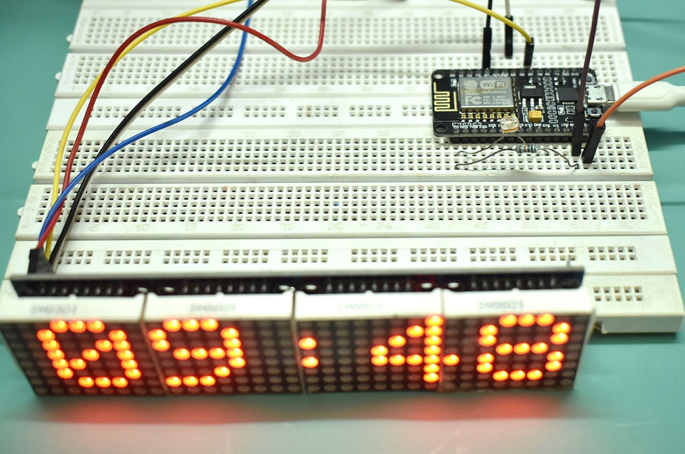
In this tutorial we are going to do is a simple connected clock that displays, on the MAX7219 LED matrix, the time, picked with NTP from web, and fixed Message for scrolling display. The display light also changed based on the light that the photoresistor measures so even if it's day or night you can read time properly and energy saver.
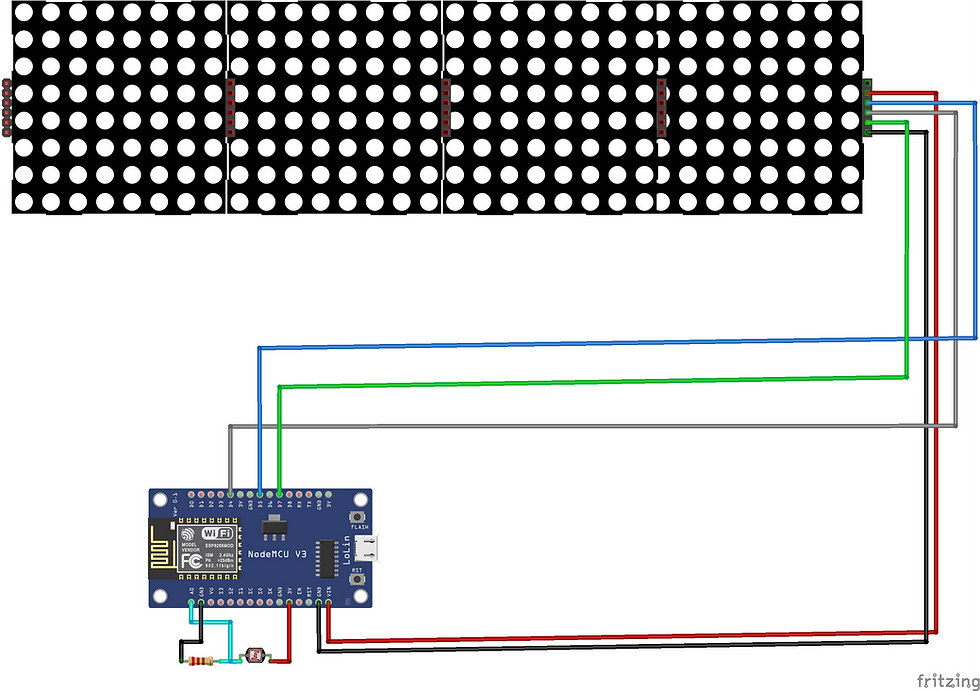
Circuit Diagram
Components Required
NodeMCU ESP8266 12E
MAX7219 dot matrix Module 4 in 1
Jumper Wires
Breadboard (optional)
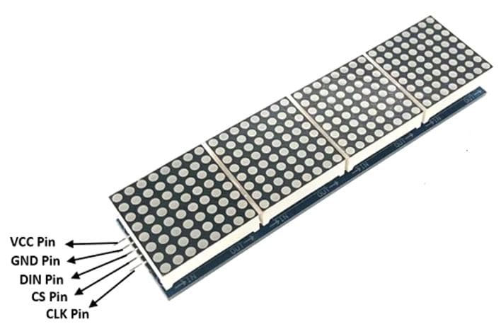
MAX7219 4-in-1 Display Dot Matrix Module
This Module is an integrated serial input/output common-cathode display driver, it connects the microprocessor 7-segment digital LED display with 8 digits, you can also connect a bar graph display or 64 independent LED. Thereon including a B-type BCD encoder chip, multi-channel scanning loop segment word driver, but also a static RAM 8 x 8 for storing each data. Only one external register is used to set the segment current of each LED.
LDR
Light dependent resistors, LDRs, or a photoresistor is a passive component that decreases resistance with respect to receiving luminosity on the component's sensitive surface. The resistance of a photoresistor decreases with increase in incident light intensity; in other words, it exhibits photoconductivity.
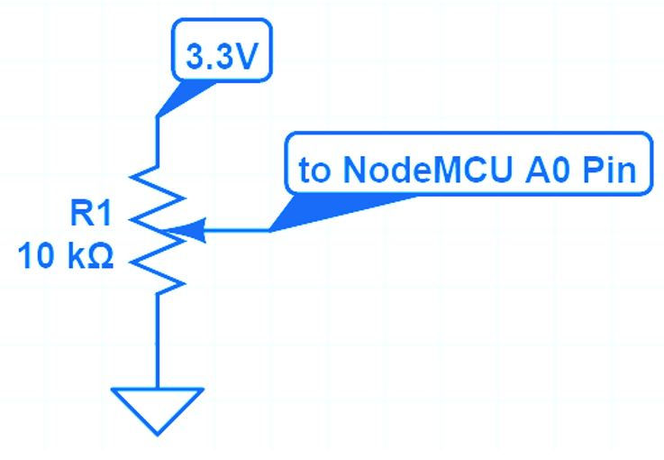
In this project, Analog pin A0 of NodeMCU is used to read Voltage in Between LDR and Series Resister for controlling the Brightness of the Matrix display. Other way to control brightness using Potentiometer and adjust brightness manually.
Installing Libraries
Download Max72xxPanel. After downloading the .zip files, add the libraries in Arduino IDE by clicking on
To install the library navigate to the Sketch > Include Library > Manage Libraries… Wait for Library Manager to download libraries index and update list of installed libraries.
Subscribe and Download code.
Arduino Code
#include <ESP8266WiFi.h>
#include <SPI.h>
#include <Adafruit_GFX.h>
#include <Max72xxPanel.h>
#include <time.h>
int pinCS = D4;
int numberOfHorizontalDisplays = 4;
int numberOfVerticalDisplays = 1;
char time_value[20];
// LED Matrix Pin -> ESP8266 Pin
// Vcc -> 3v (3V on NodeMCU 3V3 on WEMOS)
// Gnd -> Gnd (G on NodeMCU)
// DIN -> D7 (Same Pin for WEMOS)
// CS -> D4 (Same Pin for WEMOS)
// CLK -> D5 (Same Pin for WEMOS)
Max72xxPanel matrix = Max72xxPanel(pinCS, numberOfHorizontalDisplays, numberOfVerticalDisplays);
int wait = 70; // In milliseconds
int spacer = 1;
int width = 5 + spacer; // The font width is 5 pixels
int Brightness;
void setup() {
Serial.begin(9600);
WiFi.begin("TP-Link_3200","9500112137"); // your SSID, your wifi password
//CHANGE THE POOL WITH YOUR CITY. SEARCH AT https://www.ntppool.org/zone/@
configTime(0 * 3600, 0, "it.pool.ntp.org", "time.nist.gov");
setenv("TZ", "GMT-05:30",1); // INDIA //change time zone
matrix.setIntensity(0); // Use a value between 0 and 15 for brightness
matrix.setRotation(0, 1); // The first display is position upside down
matrix.setRotation(1, 1); // The first display is position upside down
matrix.setRotation(2, 1); // The first display is position upside down
matrix.setRotation(3, 1); // The first display is position upside down
matrix.fillScreen(LOW);
matrix.write();
while ( WiFi.status() != WL_CONNECTED ) {
matrix.drawChar(2,0, 'W', HIGH,LOW,1); // H
matrix.drawChar(8,0, 'I', HIGH,LOW,1); // HH
matrix.drawChar(14,0,'-', HIGH,LOW,1); // HH:
matrix.drawChar(20,0,'F', HIGH,LOW,1); // HH:M
matrix.drawChar(26,0,'I', HIGH,LOW,1); // HH:MM
matrix.write(); // Send bitmap to display
delay(250);
matrix.fillScreen(LOW);
matrix.write();
delay(250);
}
}
void loop() {
Brightness = map(analogRead(0),0,1024,0,12);
matrix.setIntensity(Brightness);
matrix.fillScreen(LOW);
time_t now = time(nullptr);
String time = String(ctime(&now));
time.trim();
//Serial.println(time);
time.substring(11,19).toCharArray(time_value, 10);
matrix.drawChar(2,0, time_value[0], HIGH,LOW,1); // H
matrix.drawChar(8,0, time_value[1], HIGH,LOW,1); // HH
matrix.drawChar(14,0,time_value[2], HIGH,LOW,1); // HH:
matrix.drawChar(20,0,time_value[3], HIGH,LOW,1); // HH:M
matrix.drawChar(26,0,time_value[4], HIGH,LOW,1); // HH:MM
matrix.write(); // Send bitmap to display
delay(3000);
matrix.fillScreen(LOW);
display_message("Welcome"); // change your text message
}
void display_message(String message){
for ( int i = 0 ; i < width * message.length() + matrix.width() - spacer; i++ ) {
//matrix.fillScreen(LOW);
int letter = i / width;
int x = (matrix.width() - 1) - i % width;
int y = (matrix.height() - 8) / 2; // center the text vertically
while ( x + width - spacer >= 0 && letter >= 0 ) {
if ( letter < message.length() ) {
matrix.drawChar(x, y, message[letter], HIGH, LOW, 1); // HIGH LOW means foreground ON, background off, reverse to invert the image
}
letter--;
x -= width;
}
matrix.write(); // Send bitmap to display
delay(wait/2);
}
}
After a successful upload, open the Serial Monitor at a baud rate of 9600. Press the “EN/RST” button on the ESP8266 board, And see the result in Dot Marix display.

Comments