Gesture Controlled Bot Using arduino & Bluetooth (Two way control)
- Ramesh G
- Nov 4, 2020
- 3 min read
Updated: Jul 2, 2021
To make a car that can be controlled using the accelerometer in a android phone. We can use the data from the accelerometer and transmit it to arduino using bluetooth module HC-05.
It will help you in building a gesture based android controlled robot without any experience in android app development by providing you the free android app.
The communication between the robot and the android application is carried over by the Bluetooth link between the phone’s Bluetooth and the Bluetooth device in the Robot. The ASCII commands are sent from the phone to the Robot which in turn checked by the Arduino for the control of the wheels according to the commands to move the robot in the desired direction.

The Following parts are required for this project:
1) Arduino Uno R3 2) HC-05 or HC-06 3) Chassis With Motors 4) Breadboard 5) L293D Motor Driver Board 6) 9V Batteries with battery Caps (2 battery and 2 caps) 7) Jumper Cables 8) Android Phone for controlling the bot
Make the circuit as is given by the circuit diagram. Make the robot assembly with your selected parts and connect the motors to the circuit.
1) The VCC of HC-05 to 5V of Arduino
2) The GND of HC-05 to GND of Arduino
3) The TX of HC-05 to RX of Arduino (Digital power pin 0)
4) The RX of HC-05 to TX of Arduino (Digital power pin 1)
Then Power on the Arduino. The HC-05 should power up if all connections are perfect. The LED on the HC-05 Module will continuously blink which means the device is now discoverable. Go to the settings of the Android phone search for bluetooth. Make sure your device is discoverable. The default name of the module is HC-05 and the default password is 1234. Pair the device with your phone. If paired Successfully you will see a change in the blinking of the LED on HC-05 Module. The LED will blink less frequently if the device is paired Successfully.
We are using L293D Motor driver Board because arduino only gives a output of 5V from the digital pins. 5V are not enough to run 2 DC motors. L293D Motor driver board gives us the option to supply power to the motors externally using a battery. If you look at the L293D carefully you will find 4 Pins for output and 4 Pins for input. Connect the Output Pins to the motors and input pins will later be connected to the arduino. There Will Also Be A Set Of Pins + and - Which Need To Be Powered By External 9V Battery.
Arduino Can be easily be programmed by using its IDE.
refer arduino iDE installion project in previous post in our website.
const int motor1Pin1 = 3;
const int motor1Pin2 = 4;
const int motor2Pin1 = 10;
const int motor2Pin2 = 11;
byte serialA;
void setup()
{
// initialize the serial communication:
Serial.begin(9600); //baud rate - make sure it matches that of the module you got:
// initialize the ledPin as an output:
pinMode(motor1Pin1, OUTPUT);
pinMode(motor1Pin2, OUTPUT);
pinMode(motor2Pin1, OUTPUT);
pinMode(motor2Pin2, OUTPUT);
}
void loop() {
if (Serial.available() > 0) {serialA = Serial.read();Serial.println(serialA);}
switch (serialA) {
case 0:
digitalWrite(motor1Pin1, LOW);
digitalWrite(motor1Pin2, LOW);
digitalWrite(motor2Pin1, LOW);
digitalWrite(motor2Pin2, LOW);
break;
case 1:
digitalWrite(motor1Pin1, HIGH);
digitalWrite(motor1Pin2, LOW);
digitalWrite(motor2Pin1, HIGH);
digitalWrite(motor2Pin2, LOW);
break;
case 2:
digitalWrite(motor1Pin1, LOW);
digitalWrite(motor1Pin2, HIGH);
digitalWrite(motor2Pin1, LOW);
digitalWrite(motor2Pin2, HIGH);
break;
case 3:
digitalWrite(motor1Pin1, LOW);
digitalWrite(motor1Pin2, LOW);
digitalWrite(motor2Pin1, HIGH);
digitalWrite(motor2Pin2, LOW);
break;
case 4:
digitalWrite(motor1Pin1, HIGH);
digitalWrite(motor1Pin2, LOW);
digitalWrite(motor2Pin1, LOW);
digitalWrite(motor2Pin2, LOW);
break;
}
}
ANDROID APPLICATION
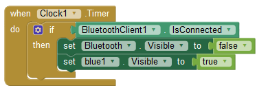
The Android app developers generally use JAVA language, but this Android app can also build without knowing the Java language. This app was developed in the online Development Environment which is developed by MIT called “App Inventor”. This app inventor is specially designed for Block programmers those who don’t know the JAVA language. The app shown below has buttons and all the buttons give different bytes in the output that has to be sent to the Arduino using Bluetooth for processing. For eg. if we press forward button, the Bluetooth Module will give 1 byte at its output, which is received by the Arduino to process the byte and take necessary action. The app consists of the option to use the accelerometer of the Android phone or to use the buttons to control the Robot. You can find tutorials related to the App inventor in its website.
Step1:

Step2:

Step3:

Step4:

Step5:

Step6:

Step7:

Step8:

Demo:
download app:
Subscribe and Download code.

Comments